お客様のご来店を歓迎します!

会員資格

助け

Hengtai Liance Instrument Manufacturing (Suzhou) Co., Ltd
カスタム製造元

主な製品:

instrumentb2b>製品
製品分類

Hengtai Liance Instrument Manufacturing (Suzhou) Co., Ltd

  • メール

  • 電話番号

  • アドレス

    No. 158 Chengsi Road, Lili Town, Wujiang District, Suzhou City

今すぐ連絡してください

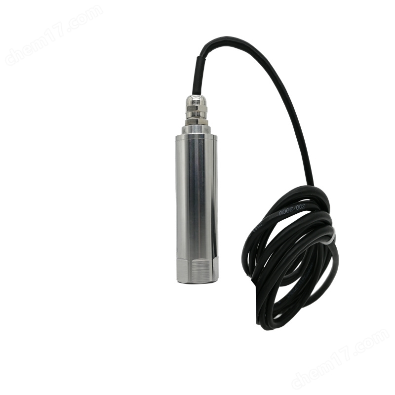
Integrated magneto electric vibration probe/sensor JMB35

ネゴシエーション可能更新05/15
モデル
メーカーの性質
生産者
製品カテゴリー
原産地

概要

Integrated magneto electric vibration probe/sensor JMB35, magneto electric vibration probe/sensor JM-B-35 integrates vibration velocity sensor and precision measurement circuit together to form a high-precision vibration measurement system ..

製品詳細

Integrated magneto electric vibration probe/sensor JMB35

The magneto electric vibration probe/sensor JM-B-35 integrates a vibration velocity sensor and a precision measurement circuit to form a high-precision vibration measurement system, realizing the function of the traditional "sensor+monitoring instrument mode vibration measurement system. The transmitter can be directly connected to DCS, PLC or other equipment, making it an ideal choice for vibration measurement of factory equipment such as fans, motors, water pumps, etc.

Technical Specifications
Power supply: 24VDC ± 10%
Input signal: taken from the signal of the built-in vibration speed sensor
Sensitivity: 20mv/mm/s ± 5%
Frequency response: 10-1000 Hz or 5-1000 Hz (special instructions)
Range: 0-20mm/s (true RMS)
0-200um (peak to peak)
Measurement error: ± 1% of full scale
Output current: 4-20mA
Output impedance: ≤ 500 Ω
Temperature range: -25 ℃ to+65 ℃ during operation
Storage time: -40 ℃~85 ℃
Relative humidity: up to 95%, non condensing
Dimensions: φ 33 × 75mm
Weight: Approximately 340g

Order code
XJ-9200A □□ (optional) - □□ (V/D) - A □□ - B □□ - C □□
Selection Guide
Optional: Waterproof connector □: F-Waterproof connector
Kaizhuang outgoing line □: B-Kaizhuang pipe
Required: Selection Description
Range □□:
Vibration velocity ranging from 10V-0 to 10mm/s; 20V*-0~20mm/s; 30V-0~30mm/s; ……
Vibration displacement ranging from 100D-0 to 100 μ m; 100D-0~200μm; 300D-0~300μm; ……
Installation direction A □:
1- Level; 2- Vertical; 3 * - Universal
Install thread B □:
1*-M10×1.5; 2-M8×1.25; 3- Magnetic seat; 4- Special customization
Cable length C □:
1-1m; 2*-2m; 3-3m; ……
Unless there are special circumstances, the manufacturer produces according to each item; If you have any special requirements, please consult with our company
Selection example: XJ-9200A-20V-A3-B1-C2
Magnetic electric vibration probe/sensor JM-B-35


Wiring method of liquid level transmitter _ Working principle of liquid level transmitter

liquid leveltransmitterWiring method

A pressure transmitter is a device that converts the pressure of a gas or liquid into usable electricitysignalThe device. Pressure transmitters can be divided into two-wire, three wire, and four wire systems according to their wiring methods. What you see should be a four wire pressure transmitter. two piecespower supplyLine, two signal lines. Power supply connected to 24V DC, simpledetectionThe method is to use onecurrentConnect the meter or voltmeter to both ends of the signal line. After the power is connected, the ammeter will have a current of 4ma or the voltmeter will have a voltage of 0V or 1V. Nowadays, there are usually four transmitters availableterminal blockTwo of them are wired, and the other two do not require wiring. They are from the transmitterDCThe 24V power line is also a 4-20mA signal feedback line, which means that your secondary meter or DAS (Data Acquisition System)AIPoint to have DC24V output.

Liquid level transmitters generally output signals with currents of 4-20mA, 0-20mA, or voltages of 0-5V, 1-5V, 0-10V, etc. The current type is usually a two-wire or four wire system, and the voltage is a three wire system output. Currently, many do not have 24VDCpower supplyThe power supply is mostly 10V, and some transmitters with high power consumption cannot be driven by a 10VDC power supply, so an external power supply of 24VDC can only be used. In this way, when the liquid level passes through Angel, four wiring terminals appear: power supply+, power supply -, feedback+, and feedback -.

Four wire wiring method for liquid level transmitter: power supply+==power supply+; Power Supply -==Power Supply -; Signal+==feedback+, signal -==feedback. liquid levelsensorThe current type two-wire connection ratio for wiring: power supply+==power supply+; Signal+==feedback+, power supply -==feedback -. If remote transmission is not required, only 24V voltage+needs to be connected. If remote transmission is needed, a circuit needs to be formed, such as 24V+connected to pressure gauge+, pressure gauge - connected to 4-20mA+, 4-20mA - connected to 24V -. There may be some issues in betweenterminalWe need to take a look at the circuit diagram.

Voltage type three wire wiring method for liquid level sensor wiring: power supply+=power supply+; Power Supply - (Signal -)==Power Supply -; Signal+==Feedback+, Power - (Signal -).

The liquid level transmitterworking principle

The working principle of the liquid level transmitter is that when two pressures of the measured medium are introduced into the high and low pressure chambers, they act on the isolation diaphragms on both sides of the δ element (i.e. the sensitive element), and are transmitted to both sides of the measuring diaphragm through the isolation diaphragms and the filling liquid inside the element.

The (floating ball) liquid level transmitter is composed of a measuring diaphragm and electrodes on both sides of the insulating filmcapacitorWhen the pressure on both sides is not consistent, it causes displacement of the measuring diaphragm, and its displacement is proportional to the pressure difference, so the two sidescapacitanceThe quantity is unequal, and through oscillation and demodulation, it is converted into a signal proportional to pressure. The working principle of pressure transmitter and pressure transmitter is the same as that of differential pressure transmitter, except that the pressure in the low-pressure chamber is atmospheric pressure or vacuum.

A/DtransformerConvert the current of the demodulator intodigital signalIts value ismicroprocessorUsed to determine the input pressure value. The microprocessor controls the operation of the transmitter. Additionally, it linearizes the sensor. Reset the measurement range. Engineering unit conversion, damping, square root, sensor fine-tuning and other calculations, as well as diagnosis and digital communication.

There are 16 byte programs in this microprocessorRAMAnd there are three 16 bit counters that perform A/D conversion.

The D/A converter fine tunes the digital signal from the microprocessor that has been calibrated, and these data can be modified using transmitter software. Data stored in EEPROMInternally, it is preserved intact even in the event of a power outage.

numbercommunicationThe circuit provides a connection between the transmitter and external devices (such as the 205 type)intelligenceCommunicators or those using the HART protocolcontrol system)The ConnectioninterfaceThis circuit detects the digital signal superimposed on the 4-20mA signal and transmits the required signal through the loopinformationThe type of communication is frequency shift keying (FSK) technology and is based on the BeII202 standard.


Integrated magneto electric vibration probe/sensor JMB35